Peak Tram track and passing loop layout
Introduction
The Peak Tram is a funicular railway, The term “funicular” is derived from Latin language meaning “rope”. It is a cable railway system that connects points along a railway track laid on a steep slope, in this case links Central (Garden Road) with Victoria Gap. The Peak Tram has two counterbalanced cars permanently attached to opposite ends of a haulage cable, which is looped over a pulley at the upper end of the track. The result of such a configuration is that the two carriages move synchronously: as one ascends, the other descends at an equal speed.
Funicular railways can have different track bed layouts. Four rails, three rails, or two rails. The principle is shown below:
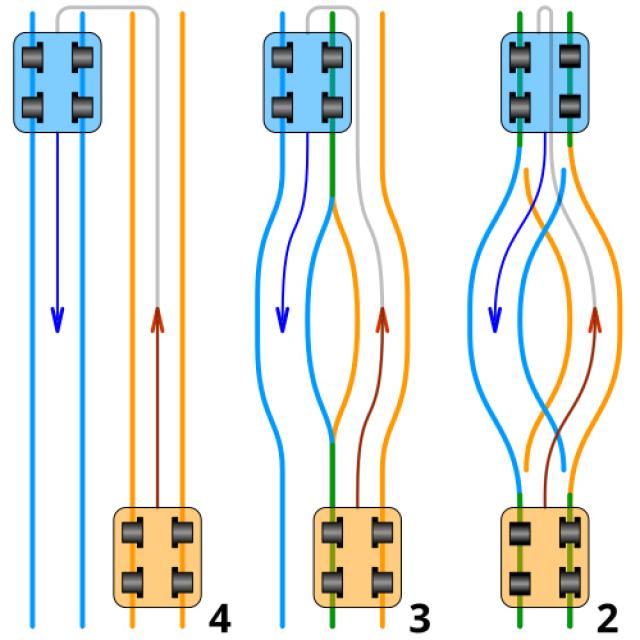
The four-rail system has two different tracks. The two cars pass by and no loop is needed. Disadvantages are the need of wider space combined with higher costs.
The three-rail system needs less space, but requires a passing loop. The two cars have separate outer rails and share the middle one, but in the loop, they have four rails.
In the two-rail system both cars share the same track except at the passing loop. It is the narrowest of all three systems but needs a more complex construction of the loop. It requires special turnout systems which ensure that the cars always enter the correct track of the loop.
In traditional funicular railways, the track system uses the same track components as found on other railways, namely sleepers, rails and small steel fittings. On lines with a steeper gradient, the sleepers are additionally secured by anchors to counteract the downward force exerted on the track by the slope. Many funicular railways, particularly those with a steep gradient, use fixed track systems.
Source and further reading: Funicular - Wikipedia
Peak Tram
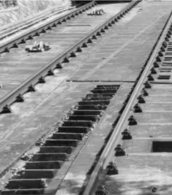
Peak Tram does have this fixed-track system (see photo below and the one from 1888 further down), probably to avoid washouts caused by rainstorms and typhoons.
When the Peak Tram was constructed, it had a combination of the two and three-rail system. The lower part had a two-rail layout, above the passing loop it had a three-rail layout.
I could not find any recent technical specifications for the tracks and loop, but there is a lot to learn from the 1887(!) French(!) Journal edition of “Nature”:
The line consists of a single track until the middle of the route, where it splits into a double track for a length of 100 meters to allow the two coupled cars, one going uphill and the other downhill, to pass each other. Above the passing point, the line continues as a double track to the arrival station, but with only three rails; the single middle rail, serving as the inner rail on each of its lateral faces, thus replaces the two inner rails that would be required for two parallel tracks. This particularly economical arrangement is quite frequently found on funicular lines operated with a single cable driven by a motor located at one end of the line, when the cable has to pull two balanced cars, each attached to one end. Compared to a single-track layout on both sides of the crossing, this design has the advantage of preventing any mixing of the two active strands of the traction cable: one ascending, the other descending. Since the winch that drives this cable is located at the upper station, the two strands thus find separate tracks, one to the right and the other to the left of the centre rail, to descend to or ascend from the crossing. When the descending end then enters the single-track section upon leaving the crossing, it occupies that section alone, as the ascending strand has already reached the upper section. When the descending strand ascends in turn, it travels along the single track before the descending strand can reach it. Each cable always retains its own dedicated track, as does the car it drives. This arrangement facilitates the branching at the crossing, since the same wagon must always turn in the same direction, and it has allowed for the installation of an automatic switch.
The situation at the three-rail part can be seen in the next photo:

In the photo we see the three rails on which the tramcars run. Then two braking rails, and the two haulage cables.
[Intermission. The tramcars normally are driven and stopped by the movement and stopping of the haulage cable. All operations are in the hand of a driver who sits in the engine room in the upper terminus. He can’t see the tram cars; he only knows their respective positions from markers on the cable. The people in front of each car are no drivers but brakesmen. They are “the eyes of the driver” and give signals if a stop is requested at one of the stations. In case of an emergency, e.g. a cable failure, the brakesmen activate an emergency brake. This consists of two steel jaws (correct term clip brake) to fasten on the braking rail. The two jaws are spring driven and are opened by hydraulic pressure activated by the brakesman who pushes down a brake bar. As soon as he removes his hand from the bar, the hydraulic pressure is released and the brake works immediately.]
The situation downhill of the passing loop can be seen in a photo from 1888. The photo obviously shows three rails, but the central one is a braking rail. The wheels of the cars run on the two outer rails.
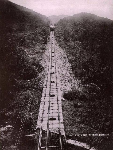
The haulage cable runs over pulleys and (in curves) over sheaves. Downhill from the passing loop only one set is required (see 1888 photo), uphill two parallel sets of pulley and sheaves are necessary.
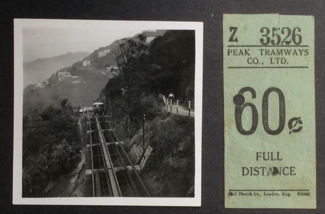
In three-rail section, one car always runs on tracks 1 and 2, whilst the other always runs on tracks 2 and 3. See photos below:
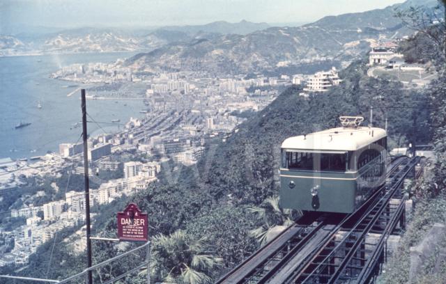
Car on tracks 1 and 2.
Car on tracks 2 and 3.
The three-rail system has one major disadvantage. At the upper terminus, only the car which runs on rails 1 and 2 stops directly at the platform:
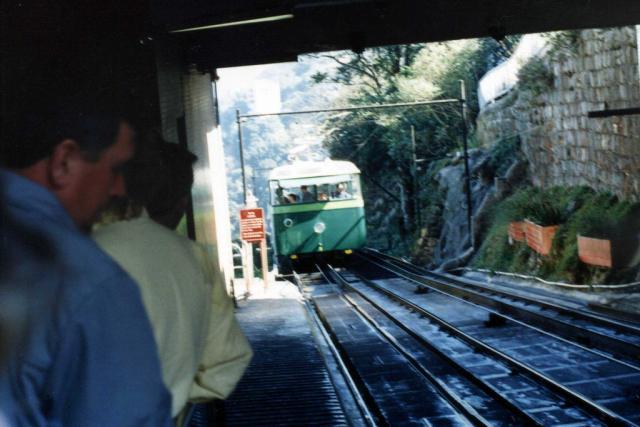
The other one (using rails 2 and 3) stops about 50 cm away (see photo below):
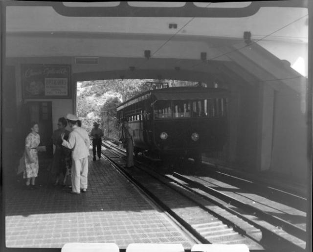
In between the rails stone slabs are laid, but passengers had to step over one rail and the braking rail to enter the car.
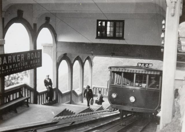
I have no idea how they managed this problem at the Barker Road Station:
Passing loop
As pointed out before, the passing loop has a combination of the two-rail layout below, four rails layout in the loop, and the three-rail layout above the loop.
The changeover from two to four rails can be seen in the photo below.
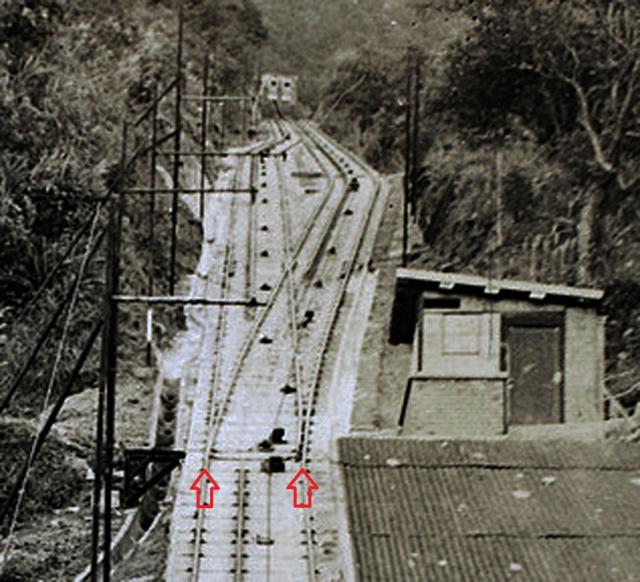
The lower two rails continue straight on the left side. The two passing rails which run to the right are only accessible via the installed switch. When looking carefully at the turnout point, the switch tongues (also called switch blades) can be seen (marked by red arrows). They direct the car running uphill (not yet arrived, still behind the viewer) to the right-hand side. This can be judged from the fact that there is no gap between the left rail and the tongue, but there is one between the tongue and the right rail. This is supported by the position of the haulage cable that also runs to the right. The downhill car that can be seen in the photo will take the left track in the loop.
A switch needs to be operated, either by hand or via motor-operated remote control. In the early days, this had to be done manually. It looks as if this also was necessary for the Peak Tram from the start in 1888, possibly up to the 1950s. (Booth described his view looking uphill from the May Road Bridge over the Peak Tram: "a small signal box in which a man changed the points at the passing place".
This is possibly the man in white uniform who was standing next to the tramcar.

The lower entrance to the passing loop can also be seen again in the photo below. It was taken on 1 April 1989, shortly before the 1989 renovation (see below).

Here is the switch and its operator. It seems that, even 100 years after it was first put into service, the switch still needs to be operated manually. The photo was likely taken from an uphill tramcar. After passing the switch, the operator has already moved the tongues (blades)(red arrows) for the downhill tramcar which will arrive soon from the left. It seems that the switch now is motor driven (box on the right next to the track), but still a person sitting there had to activate it.
The situation uphill from the loop is somewhat less complex (see photo below, it shows the view downhill):

In the loop, there are four rails that become three above the loop. The rails number 2 and 3 merge where the red arrow is. Here the main advantage of the three-rail arrangement can be seen.: no movable parts are necessary. At the point of the red arrow, the number 2 rail continues straight ahead. Also at this point, a new rail turning right (which will become number 3) is welded to the one continuing straight ahead (or possibly the y-shaped rail is forged in one piece). What is the reason for this arrangement?
To understand the principle, we must know the design of the wheels. A typical wheelset has two wheels mounted rigidly to an axle. To keep the rails on track, they have flanges on each inner side of the wheels (see the schematic drawing below).

The photo of the track layout at the upper entrance to the passing loop was taken from a tram car (assuming it was descending) which ran on rails 2 and 3 (i.e. on the right-hand side). The only direction possible for this car is to run right. Why? The inner flanges of the wheels force the car to turn right at the place where the red arrow is. The car will continue downhill on rails 3 and 4 (numbering in the four-rail section).
The ascending tramcar will arrive on the left side on rails 1 and 2 (numbering in the four-rail section). It continues straight ahead and will not be affected by the joint of the turning rail (red arrow) because the inside wheel flanges direct the car to go straight ahead.
These procedures are repeated in the opposite direction.
1989 renovation
This situation changed later, likely during the 1989 major overhaul. Not only new (red) tramcars came into service, also the track layout was changed.
A major improvement was a replacement of the movable switches at the passing loop by a non-moving system. It was already invented in 1879 by the Swiss engineer Carl Roman Abt and therefore commonly known as Abt’s switch.
The principle is comparably simple: the commonly used wheelset (see above) is replaced by one where the outboard wheels have flanges on both sides, whereas the inboard wheels are unflanged (and usually wider to roll over turnouts more easily). The double-flanged wheels keep the carriages bound to one specific rail at all times. An example is shown below

The principle of the switch can be seen in the photo below. For better understanding, colour marks are used.

The photo shows the entry to the passing loop uphill from the May Road station. The guiding or leading rails are marked in red, the non-guiding ones are blue and green, and the traction cable is yellow.
Assuming an ascending tramcar, it will arrive from below on the rails marked in red. It must follow the direction of the traction cable (marked in yellow). The double-flanged wheel on the left will continue straight ahead at the switch point. The wider wheel on the right will pass from the red to the green rail and continues ascending. The wheel is not affected by the gap because it is wide enough (see photo above). Ahead of the tramcar, of course, the traction cable has left the switch.
The descending tramcar will arrive from above on the blue rail and the upper red rail (on the right). As the tramcars always have double-flanged wheels on the outer side, the descending tramcar will follow the right red rail all the way. The other (wider) wheel will continue on the blue rail until it reaches the switch point and will pass over to the (left) red rail. Behind the tramcar, the traction cable will follow, supported by the pulleys which can be seen in the photo.
Another feature of the track has changed, the two braking rails have been removed.
Another important change occurred above the passing loop. The original three-rail design continues as before in the curve in the tram track. Uphill from the curve, the three-rail section changes into a two-rail one (via an Abt’s switch). The main advantage is at the stations (Barker Road and Victoria Gap) that both tramcars have the same distance to the platform without a gap.

At the upper terminus, two platforms were built: on the right for entering, on the left for leaving the tramcar.
The Peak Tram Upgrade Project
This project was executed between 2019 and 2022 with a 3 and a 14-month closure. During this time, tracks and foundations were replaced, the two terminus stations were rebuilt, the passing loop restructured and new, longer cars were installed. The new Peak Tram opened on the 2 December 2022.
Further reading:
The Peak Tram – How it works – The Industrial History of Hong Kong Group
How does the Peak Tram cross in the middle? - Checkerboard Hill
Braking Rail - 100 years (1989)
As a child, I was told the tram won't roll down the slope if the cable snaps, because of the braking rail and the two spring driven jaws. In the 60s, if I remember correctly, the driver was always holding on to a bar which control the jaws and/or the brake.
Now that the braking rail had gone since 1989, I am even more skeptical, about those sensor driven microprocessor control braking motors, may be due to my old age !
The modern peak tram is now 2-3 times heavier than old ones.
The Modern Safety Mechanisms
Multiple Brake Systems: Standard funiculars employ four or more independent fail-safe brakes, including track-clamping emergency brakes that trigger if the cable breaks or the car speeds.
Auxiliary Power: In the event of primary power outages, auxiliary diesel engines or hydraulic systems are built in to slowly drive cars to safety.